Wednesday 29 February 2012

Model Workshop 3

Last day of the Model Workshop and seeing as I got all the pieces fabricated yesterday, today was just spraying. Having got rid of some defects yesterday through sanding today started with another coat of primer, finishing the undercoat.
 With the undercoat finished I began applying my colour scheme. I chose to have the body a matte black, with the buttons in red and the wheel holder in white. This gave me a variety of colours and textures , with the red and white providing spot colours and contrast to the black body and wheel.
So after roughly three coats the colour was finished without too much trouble (although the red did splatter all over my lab coat) to a suitable quality and, because of the long drying time for the paint (its touch dry after 10 mins but takes 4 hours to dry properly) all that remained was to hand over the pieces to Paul the technician for him to glue together and mark tomorrow.
So as far as this project is concerned all that remains is to pick it up on Friday, where I'll be able to show it in it's fully assembled form.

Tuesday 28 February 2012

Model Workshop 2

So returning from where I left off yesterday, this is the shape of my (computer) mouse model looking very much like an Apple mouse (button less), but that will change today.

The first job was to mark out  and mill on the body the slot for the holder for the scrolling wheel. The marking out was done with a digital vernier and then the material was removed on the milling machine creating...
...this lovely gap here.
To fill the gap I began work on the holder for the wheel. Starting off with a simple block I cut and sanded it down so that it fitted neatly in the hole with approx. 1/2mm gap round it (this actually took two attempts as the first was too small)
 With the holder temporarily done, I set to work on making the buttons. To do this I had to first prise apart the two parts of the model and, making a substitute base out of pink foam, cut across and down the top piece splitting it into the body and two buttons. This was done on a fret saw and was quite nerve-racking as there was very little room for error.
That done I returned to the scrolling wheel holder where again using the milling machine I cut a groove and created an indent.
 So the final setup of the pieces looks like this both dismantled and together (OK minus the ABS base and the scrolling wheel itself)
So the final work I got done today was starting to paint the model. First each component was mounted onto a wooden stand and then I applied the first coat of a grey primer using a spray gun. The paint emphasises any mistakes made so I then took a couple of pieces back to the workbench to sand out a couple of holes before applying a second coat of primer.
So nearly done then, just the painting to finish tomorrow, so it shouldn't take too long (good as I have lots of other work to get on with)

Monday 27 February 2012

Model Workshop 1

So the second to last of the workshops I am doing this year, model making. This is, like the plastic workshop, only a short workshop, and so it will be finished, one way or another, by Wednesday afternoon. The aim of the workshop is to test our abilities in working with the material and creating a good finish on the model.
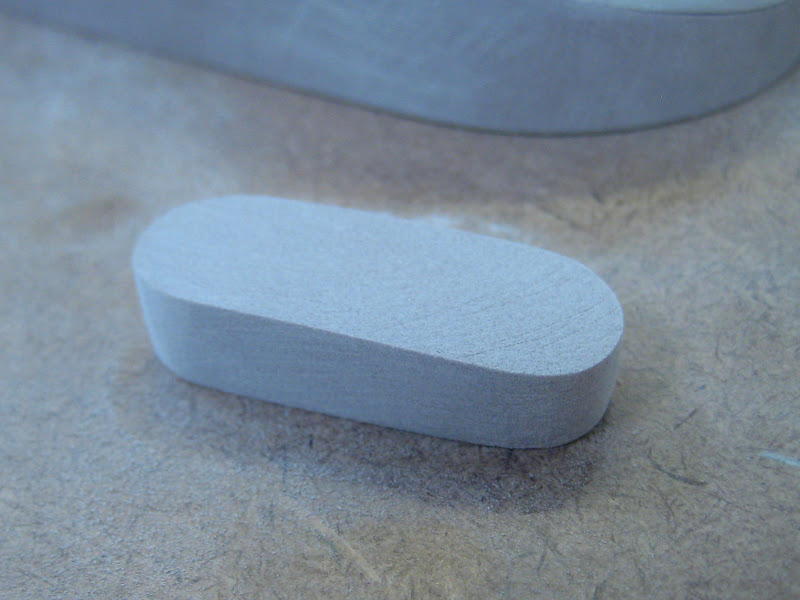
So the item I am making is a non-working model of a computer mouse, out of Polyurethane Modelling Board (Uriel) and is a type of very dense plastic foam. At the start of the day were were given the above block which will form the majority of the model.
The first job was, using a pre-drawn orthographic drawing of the model, cut out the main parts of the model, this being the top piece, forming the buttons and the top, and the base. To do this the drawing was stuck to the model and used as a guide on the band saw before cleaning on a disk sander.
With the parts cut out, a layer of wax was applied to the top of the base and a layer of filler to the bottom of the top piece. This creates a perfect fit and neutralises the jagged edges from the cutting (the wax is to stop the filler fixing to the bottom layer).
While the filler was drying I cut out a piece of plastic to go on the bottom of the base to hold the model slightly off the ground. This was cut on a bench saw out of black ABS.
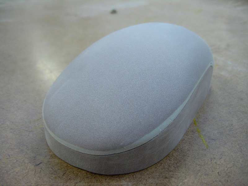
With the filler dry and the excess sanded off, the two pieces now form a perfect fit.
The final stage I got to today was to sand it down to a smooth finish on top, exactly copying the design. This was done first on the disk sander, then with different grade sandpaper from shaping with 120 to finishing with 1200. So at the end of today what I have is effectively a brown version of the Apple Magic mouse as the photos below show.

And finally the photo below is of the area where I was working. As you can see I used lots of sandpaper (getting through 4 sheets of the 120 grade alone) and it was very dusty.
So more work on it tomorrow where hopefully I will get the buttons and clicker wheel made and begin painting it.

Sunday 19 February 2012

Mechanics Tensile Lab Test

This week I had to hand in a Laboratory Report. The lab was on material tensile strength, looking at the stress/strain graphs exhibited by different grades (Carbon percentage) of mild steel. The machine we used was a Hounsfield Tensometer.
A part of the report was to describe and explain the equipment used in the experiment. To accompany the text I wanted some images, but I was unable to find images that represented the equipment with any sort of cohesion. To solve this I decided to take the best images I could find, whether sketches, technical diagrams or a couple of photos taken by me, and use Illustrator to create some simple vector outlines.


These show the different equipment used from the top, the Hounsfield Tensometer, the samples used, a Tinsley Strain Measurement Bridge, Ultimate Area Reduction Gauge and Ultimate Elongation Gauge.
Below are a couple of pictures I took of the experiment at the time, they weren't too good but I did use the one on the right for the Bridge.
Finally a couple of graphs from the results of the experiments. The one on the left shows the stress/strain curves of 0.1%, 0.2%, 0.4% and 0.8% Carbon Steel, while the one on the right is the Elongation, Yield Strength and Ultimate Tensile Strength against the increasing Carbon %.

Friday 10 February 2012

Eco-Design Presentation Board

So the deadline for the Eco design critique was today and this below was my idea.
The ideas was to use new technology in harvesting Spider Silk to create reusable bags that can also be easily stored and carried about. This could be applied to other products and would reduce our reliance of natural oil plastics. However the main purpose of the crit was to evaluate our concept presentation skills, and as such a lot of emphasis was placed on the layout and graphics of the boards rather then the actual concept. As you can see I took a bit of a gamble as I decided against the normal clean white perfect background and grid based layout in favour of a more unusual layout. However I have to admit I'm not sure if it has payed off and I will be rethinking the idea for the final deadline in April based upon what was said in the critique.

Below is some of the content I edited and created for the board.

Monday 6 February 2012

Plastics Workshop- Clock

So this is the result of 2 1/2 days spent in the plastics workshop.
The brief was simply to make a clock out of plastic using a simple mechanism in the allotted time.I started with some quick sketches, at one point expanding on the idea of an exploding clock face, but what I really wanted was for the clock to have a more sculptural feel, taking full advantage of it's position as a desk clock to expand more than just a flat 2D surface.
Eventually my thinking brought me to a science inspired design, taking inspiration from the rings and orbits of planets, and more acutely from the structure of atoms, resulting in the design below.
The construction of this was both simpler and more complex than I expected, with some aspects being very frustrating.
 The first job for me was to assemble all the sheets of acrylic I would need and to mark out and cut them down to approximately the right sizes. Annoyingly once this was done I was finished for the day as the workshop technician then glued the sheets together to make the blocks I would then shape, and this had to dry overnight.
 So the next day with the blocks dry, I began shaping them, first on the band saw, and then on a lathe. This was much easier than I had anticipated due to the accuracy of the machines. The rings cut I then shaped the clock face and base further on the lathe, before milling out the space for the clock mechanism on the back of the face on a milling machine.
 Finally I then began cleaning up the components, first with wet and dry paper and then on a buffing machine. This was particularly difficult with the rings as occasionally the machine would rip the ring out of my hands and send it across the room. The pieces finally clean, I then stuck them together using a polycement glue, just in time for the deadline.